Articles

The SLAB Memory Allocator

One of the primary things an operating system does is allocate memory. In this tutorial we’re going to write our very own memory allocator for the rest of the kernel to use to allocate memory. This will allow us to more safely use and allocate strings and implement more complicated data structures which will come in useful later!

Allocate this thing!

In this tutorial I’m going to focus on the SLAB Memory Allocator used in the Linux operating system which eliminates memory fragmentation caused by allocations and deallocations. In an operating system this is usually built on top of the Virtual Memory system which maps 4KB blocks of memory. This means the goal of the allocator is to chop those 4KB blocks up into more manageable pieces.

The virtual memory system provides an API where you can map a 4K block of memory to a specific memory address. In my kernel it looks like this:

void map_page(u32 virtualAddr);

If you fail to call map_page and attempt to read/write from a memory location that isn’t mapped then you get a page fault. I plan to talk in more detail about the virtual memory system in a future tutorial.

Allocator API

First off let’s define the interface to our memory allocator. We don’t want to confuse it with malloc so I’ve gone with kalloc. I also like to avoid sprinkling unsigned everywhere so let’s add some typedefs.

typedef unsigned int u32;
typedef unsigned short u16;

void kalloc_init(u32 memStart, u32 memSize);
void* kalloc(u32 size);
void kfree(void* ptr);

kalloc_init allocates a range of memory and sets everything up. We would call this from our kernel setup routine after we’ve initialised the virtual memory system.

Slab Algorithm

The core idea of the SLAB allocator is that you split each 4K block (from now on a Slab) into an array of blocks of the same size. For example a 4K slab can hold exactly 4 x 1024 byte objects and 32 x 128 byte objects. To avoid wasting space the object size must be a power of 2.

When you request a block of memory of a specific size the allocator finds a slab with objects that are the next power of 2 of that size and hands you a free block from it. If there are no free blocks left then a new slab is mapped from virtual memory.

Free memory inside a slab is tracked via a linked list where the pointer to the next free element is stored inside the free memory location itself! This constrains us to a minimum allocation size of 32 bits so we can store the pointer.

Allocation within a Slab

Allocation within a Slab

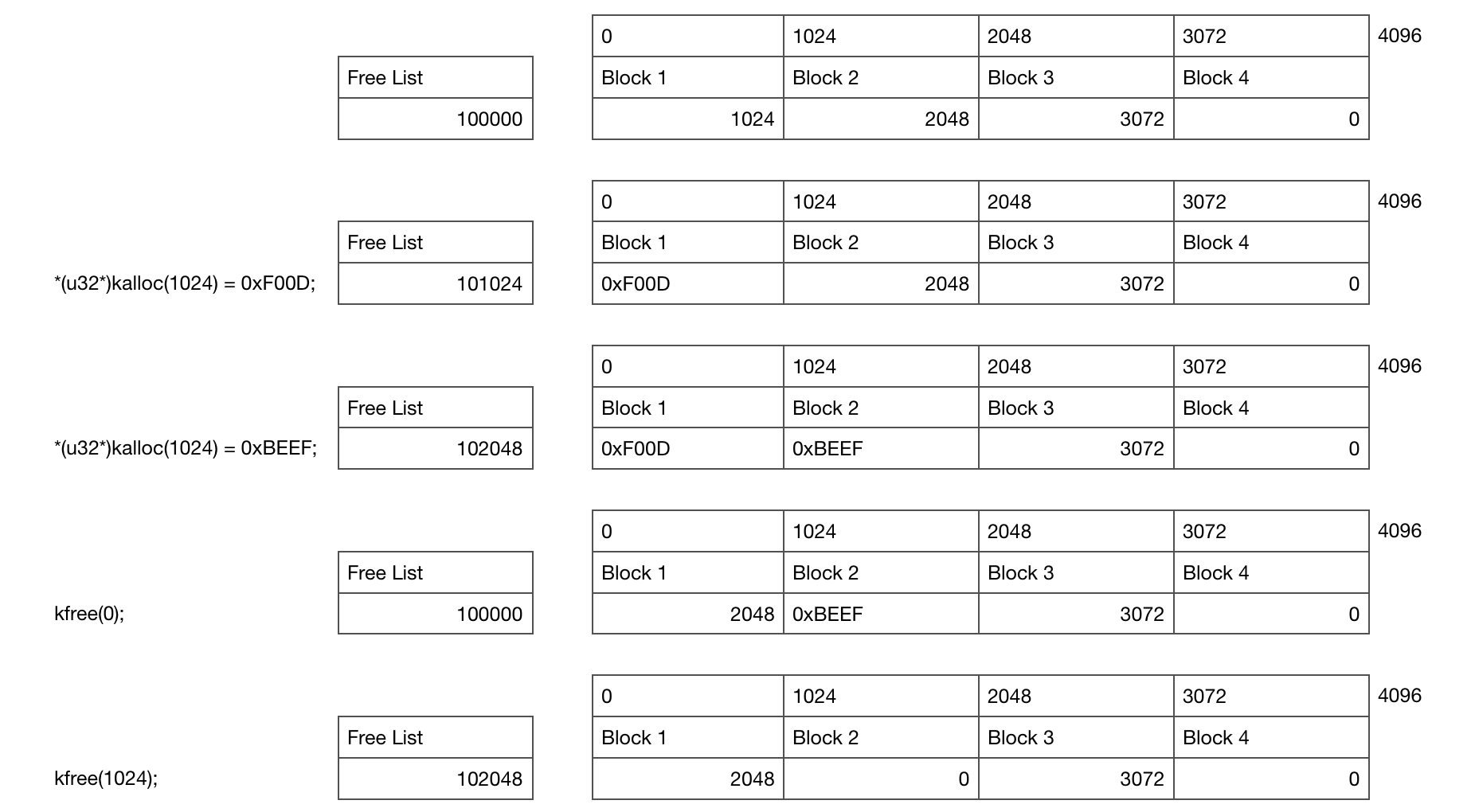
This diagram shows what’s going on for a single Slab as you allocate and free memory. In this example you start with a single 4KB Slab containing 4 x 1KB objects which has been allocated at location 10000 in memory. An unaligned low memory location like this is a bad idea in the real world but this makes it easier to understand ;)

Initially the free list is pointing at the first block, which is pointing to the second block and so on until we hit the null pointer at the end.

The first kalloc allocates 1KB of memory and writes 0xF00D to it which updates the free list pointer to point at the second block of memory. The second writes 0xBEEF and points the free list at the third block.

When the memory is freed we simply write the free list location into the freed memory location and update the free list to point at our freed block.

Let’s go ahead and write some code for this!

struct SlabEntry
{
    SlabEntry* next;
};

struct Slab
{
    Slab* m_nextSlab;
    SlabEntry* m_freeList;
    u32 m_slabStart;
    u16 m_size;

    void Init(u32 slabStart, u16 size);
    bool Alloc(u32 size, u32& newLoc);
    bool Free(u32 location);
};

First we need to initialise the memory for a single slab by setting up the free list to point to each block of free memory. Initially this will be every block of memory in the slab, like this:

void Slab::Init(u32 slabStart, u16 size)
{
    m_nextSlab = nullptr;
    m_slabStart = slabStart;
    m_size = size;

    map_page(slabStart);
    memset((void*)slabStart, 0, 0x1000);

    u32 numEntries = (0x1000 / size) - 1;
    m_freelist = (SlabEntry*)slabStart;
    SlabEntry* current = m_freelist;
    for (u32 i = 1; i<numEntries; i++)
    {
        current->next = (SlabEntry*)(slabStart + (i * size));
        current = current->next;
    }
}

This function takes a virtual memory location which we will ask to be managed by this slab and the size of each object we’ll be allocating. We ask the virtual memory paging system to map this page for us and make it writeable.

Next the alloc function pops a free object off the free list!

bool Slab::Alloc(u32 size, u32& newLoc)
{
    if (m_size != size || m_freelist == nullptr)
        return false;
    newLoc = (u32)m_freelist;
    m_freelist = m_freelist->next;
    return true;
}

The free function adds an object back on the free list, after checking that the memory location being freed is within the slab:

bool Slab::Free(u32 location)
{
    if (location < m_slabStart || location >= m_slabStart + 0x1000)
        return false;
    SlabEntry* newEntry = (SlabEntry*)location;
    newEntry->next = m_freelist;
    m_freelist = newEntry;
    return true;
}

There is a whole bunch of extra checks you can do here which I’ve left out to make the code simpler.

Allocating Slab Metadata

So at this point we have a way of allocating memory for a single 4KB block of memory for a single allocation size. How do we build on this?

We want to support multiple slabs of memory! The simplest option is to have a linked list of them, like this:

Slab* g_slabList;

This brings up another problem. Where do we store the members inside each Slab struct? The answer is to store the Slab structs inside a special list of Slabs set aside just for this purpose - a ‘metadata’ slab.

Slab* g_slabMetaData;

Here is helper function alloc_slab_meta that will set one of these up. The trick here is to use the first object in the slab to store the fields of the metadata slab itself. It’s turtles all the way down!

static Slab* alloc_slab_meta(u32 slabStart)
{
    Slab slabMetadata;
    slabMetadata.Init(slabStart, sizeof(Slab), true);
    u32 slabLoc;
    bool didAlloc = slabMetadata.Alloc(sizeof(Slab), slabLoc);
    assert(didAlloc && slabStart == slabLoc);

    Slab* newSlabMeta = (Slab*)slabLoc;
    *newSlabMeta = slabMetadata;
    return newSlabMeta;
}

Putting it all together

We need to know where our heap needs to start from in virtual memory:

u32 g_memStart;

We’re ready to write our kalloc function! First we loop through the existing slab lists to see if we can allocate memory from those:

void* kalloc(u32 size)
{
    u32 newLoc;
    Slab* slab = g_slabList;
    for (; slab; slab = slab->m_nextSlab) {
        if (slab->Alloc(size, newLoc)) {
            return (void*)newLoc;
        }
    }

If that fails then we need to allocate a new slab, and hand over the first block of memory from there. The memory for slabs is held by the g_slabMetaData which we can now allocate from:

u32 slabLoc;
bool didAlloc = g_slabMetaData->Alloc(sizeof(Slab), slabLoc);

If the metadata is full then we need to allocate a new metadata slab! Since this allocator never throws away allocated slabs we don’t need to keep a reference to previous metadata slabs.

if (!didAlloc) {
    g_slabMetaData = alloc_slab_meta(g_memStart);
    g_memStart += 0x1000;
    g_slabMetaData->Alloc(sizeof(Slab), slabLoc);
}

Now we have somewhere to put the metadata we can allocate a new slab and add it to the slab list!

Slab* newSlab = (Slab*)slabLoc;
newSlab->Init(g_memStart, size, false);
g_memStart += 0x1000;
newSlab->m_nextSlab = g_slabList;
g_slabList = newSlab;

Now we can allocate the block of memory inside the slab.

    newSlab->Alloc(size, newLoc);
    return (void*)newLoc;
}

I have intentionally kept the code here simple meaning there is a lot of room here for optimisation. For example you could maintain multiple slab linked lists allowing you to skip over slabs that are full or find a slab with the correct allocation size more quickly.

I’ve also missed out some asserts and other safety checks. I’ve included those in the full version below.

Freeing memory

To keep things simple we’re only going to free memory inside each slab - once a slab has been allocated it is alive forever! A more fancy version would throw away everything that’s been allocated.

The free function simply asks each slab if it wants to free the block. Again you could be much cleverer and have multiple lists so you can find the slab much more quickly.

void kfree(void* ptr)
{
    if (!ptr) 
        return;

    u32 loc = (u32)ptr;
    for (Slab* slab = g_slabList; slab; slab = slab->m_nextSlab)
        if (slab->Free(loc))
            return;
}

Final bits

That’s the core stuff! All we need now is an init function and a main function to test this thing. The init function allocates the first metadata block and sets up the globals.

void kalloc_init(u32 memStart, u32 memSize)
{
    g_memStart = memStart;
    g_slabList = nullptr;

    g_slabMetaData = alloc_slab_meta(g_memStart);
    g_memStart += 0x1000;
}

You don’t need your very own operating system to test this! We can point this code at a block of memory, like this:

char g_memory[1024*1024];// 1 MB!

int main(int argc, char** argv)
{
    kalloc_init(&g_memory[0], sizeof(g_memory));
}

You can download the whole file here and then compile and run it like this:

gcc kalloc.cpp --std=c++11 -m32 -o kalloc && ./kalloc

This also includes a couple of simple test routines. Note there are almost certainly bugs - please don’t use this in code you care about ;)

Conclusion

So that’s how the slab allocator works which concludes this tutorial!

In a future tutorial series I’m going to talk about setting up virtual memory and interrupts. You might also be interested in the previous tutorial series I wrote on how to write a bootloader!.

Writing a Bootloader Part 3

In our previous article we got our CPU into 32-bit protected mode and printed the screen using the directly mapped VGA memory. This time we’re going to compile and load a C++ function into memory and call it!

Going beyond 512 bytes

The BIOS only loads the first 512 bytes of the bootsector. If we want to write programs larger than 512 bytes (maybe you don’t want to and like a challenge?) we’re going to have to load more off the disk. To do this we’re going to use the int 0x13 interrupts which provide disk services.

The ah=0x2 int 0x13 command reads sectors from a drive to a target location, like this:

mov ah, 0x2    ;read sectors
mov al, 1      ;sectors to read
mov ch, 0      ;cylinder idx
mov dh, 0      ;head idx
mov cl, 2      ;sector idx
mov dl, [disk] ;disk idx
mov bx, copy_target;target pointer
int 0x13

The disk number is implicitly placed into dl by the BIOS on startup. Earlier on we stashed it into memory with mov [disk], dl.

So we can now load 512 bytes from the second sector into memory! Let’s make use of that and move the hello world printing code from last time beyond the first 512 bytes of disk. Like this:

times 510 - ($-$$) db 0
dw 0xaa55
copy_target:
bits 32
    hello: db "Hello more than 512 bytes world!!",0
boot2:
    mov esi,hello
    mov ebx,0xb8000
.loop:
    lodsb
    or al,al
    jz halt
    or eax,0x0F00
    mov word [ebx], ax
    add ebx,2
    jmp .loop
halt:
    cli
    hlt
times 1024 - ($-$$) db 0

The last line pads our bootloader to 1024 bytes so we’re not copying uninitialised bytes from disk. It’s probably easiest to download boot3.asm directly. You can compile and run it with nasm -f bin boot3.asm -o boot.bin && qemu-system-x86_64 -fda boot.bin getting this result:

Hello more than 512 bytes world

Getting to C++

Next we’re going to load a C++ function that prints Hello world into memory and then call it from the bootloader. Here is the C++ function we want to compile:

extern "C" void kmain()
{
    const short color = 0x0F00;
    const char* hello = "Hello cpp world!";
    short* vga = (short*)0xb8000;
    for (int i = 0; i<16;++i)
        vga[i+80] = color | hello[i];
}

I’ve intentionally kept the function as simple as possible - it does almost the same thing as the assembly code. The extern "C" prevents C++ from name mangling the function allowing us to call it from assembly.

Compiling and Linking

We now need to compile and link this function. To do this safely we need to create a cross compiler - this is safer than using your system’s C++ compiler since we can be certain about what instruction set and function call method the compiler uses. I also can’t for the life of me convince clang to use a linker script and stop adding loads of OSX specific stuff. Since we’re building a 32 bit operating system we also want the compiler to output 32 bit instructions - not 64 bit ones!

Compiling a cross compiler is an absolute pain - but luckily I’ve hacked a homebrew tap you can use:

brew tap zanders3/homebrew-gcc_cross_compilers
brew install --debug i386-elf-gcc

Interestingly upgrading Mac OSX can mess gcc and all sorts of things up so try these commands if things fall over.

xcode-select --install
brew reinstall gcc

This will install i386-elf-_g++ on your path which will compile and link stuff for us! Installing takes a while - you might want to grab a cuppa whilst it compiles.

Linker Script

We need to tell gcc how to link our cpp file and asm files together. We want the boot4.asm code positioned at offset 0x7c00 so that the 510th bytes equal 0xAA55 which makes it a valid bootsector. We then want all of the C++ code placed after that in the file.

ENTRY(boot)
OUTPUT_FORMAT("binary")
SECTIONS {
    . = 0x7c00;
    .text :
    {
        *(.boot)
        *(.text)
    }
    .rodata :
    {
        *(.rodata)
    }
    .data :
    {
        *(.data)
    }
    .bss :
    {
        *(.bss)
    }
}

The ENTRY(boot) means the entry point of the program is the boot symbol. OUTPUT_FORMAT("binary") tells gcc to output raw assembly directly. It will otherwise output a binary file in ELF. The . = 0x7c00 tells it to start outputting code at that offset, similar to the org 0x7c00 command.

Calling C++ from Assembly

Next we need to modify our assembly so it can be linked with gcc. First we’re going to put everything in the .boot section so it’s placed first as well as define a global boot: symbol so the linker knows about the entry point.

section .boot
bits 16
global boot
boot:

Next we’ll hack the disk reading function call to load more than one sector:

mov al, 6      ;sectors to read

Finally we set up a call stack for C++ to use and call the actual function. We reserve 16 KB for a kernel call stack.

mov esp,kernel_stack_top
extern kmain
call kmain
cli
hlt
section .bss
align 4
kernel_stack_bottom: equ $
    resb 16384 ; 16 KB
kernel_stack_top:

That’s it. We’re ready to compile and run this thing! Here are my versions of the linker script, cpp file and bootsector assembly!

Compiling and Running

You want to compile the assembly, then link it all together.

nasm -f elf32 boot4.asm -o boot4.o
i386-elf-_g++ x86_64-elf-g++ -m64 kmain.cpp boot4.o -o kernel.bin -nostdlib -ffreestanding -std=c++11 -mno-red-zone -fno-exceptions -nostdlib -fno-rtti -Wall -Wextra -Werror -T linker.ld

We can run hexdump kernel.bin to check it did the right thing:

0000000 b8 01 24 cd 15 b8 03 00 cd 10 88 16 61 7c b4 02
0000010 b0 06 b5 00 b6 00 b1 02 8a 16 61 7c bb 00 7e cd
0000020 13 fa 0f 01 16 5b 7c 0f 20 c0 66 83 c8 01 0f 22
0000030 c0 b8 10 00 8e d8 8e c0 8e e0 8e e8 8e d0 ea 22
0000040 7e 08 00 00 00 00 00 00 00 00 00 ff ff 00 00 00
0000050 9a cf 00 ff ff 00 00 00 92 cf 00 18 00 43 7c 00
0000060 00 00 00 00 00 00 00 00 00 00 00 00 00 00 00 00
*
00001f0 00 00 00 00 00 00 00 00 00 00 00 00 00 00 55 aa
0000200 48 65 6c 6c 6f 20 6d 6f 72 65 20 74 68 61 6e 20
0000210 35 31 32 20 62 79 74 65 73 20 77 6f 72 6c 64 21
0000220 21 00 be 00 7e 00 00 bb 00 80 0b 00 ac 08 c0 74
0000230 0d 0d 00 0f 00 00 66 89 03 83 c3 02 eb ee bc f8
0000240 be 00 00 e8 02 00 00 00 fa f4 55 48 89 e5 48 83
0000250 ec 20 c7 45 f8 00 0f 00 00 48 c7 45 f0 ad 7e 00
0000260 00 48 c7 45 e8 00 80 0b 00 c7 45 fc 00 00 00 00
0000270 83 7d fc 0f 7f 34 8b 45 fc 48 63 d0 48 8b 45 f0
0000280 48 01 d0 0f b6 00 66 98 80 cc 0f 89 c2 8b 45 fc
0000290 48 98 48 83 c0 50 48 8d 0c 00 48 8b 45 e8 48 01
00002a0 c8 66 89 10 83 45 fc 01 eb c6 90 c9 c3 48 65 6c
00002b0 6c 6f 20 63 70 70 20 77 6f 72 6c 64 21 00 00 00
00002c0 14 00 00 00 00 00 00 00 01 7a 52 00 01 78 10 01
00002d0 1b 0c 07 08 90 01 00 00 1c 00 00 00 1c 00 00 00
00002e0 6a ff ff ff 63 00 00 00 00 41 0e 10 86 02 43 0d
00002f0 06 02 5e c6 0c 07 08 00                        
00002f8

Note the 55 aa there near offset 0x200? That means it’s a valid bootsector! Let’s try running it with qemu-system-x86_64 -fda kernel.bin and you should get this result.

Our Hello CPP world bootloader

Wrapping Up

That concludes this tutorial series! I hope this was useful to you.

There many more interesting low level things to explore such as setting up virtual memory, handling interrupts and writing your very own memory allocator! I hope to start exploring these in the future.

Writing a Bootloader Part 2

In our previous article we described how to write a bootloader that prints ‘Hello World!’ to the screen in 16bit Real Mode. We’re now going to one up ourselves and print ‘Hello World!’ from 32 bit Protected Mode!

Entering 32-bit Mode

In our previous article the CPU was still in Real Mode - this means you can call BIOS functions via interrupts, use 16 bit instructions and address up to 1 megabyte of memory (unless you use segment addressing). To access more than 1MB of memory we’re going to enable the A20 line by calling the ‘A20-Gate activate’ function. To do this we’ll create a new file called boot2.asm and put this in there:

bits 16
org 0x7c00

boot:
    mov ax, 0x2401
    int 0x15 ; enable A20 bit

Whilst we’re here we’ll also set the VGA text mode to a known value to be safe. Who knows what the BIOS set it to!

mov ax, 0x3
int 0x10 ; set vga text mode 3

Next we’ll enable 32 bit instructions and access to the full bit 32 registers by entering Protected Mode. To do this we need to set up a Global Descriptor Table which will define a 32 bit code segment, load it with the lgdt instruction then do a long jump to that code segment.

lgdt [gdt_pointer] ; load the gdt table
mov eax, cr0 
or eax,0x1 ; set the protected mode bit on special CPU reg cr0
mov cr0, eax
jmp CODE_SEG:boot2 ; long jump to the code segment

Global Descriptor Table

The GDT we’re going to set up involves 3 parts: a null segment, a code segment and a data segment. The structure of each GDT entry looks like this:

GDT Entry Layout

Here’s what the fields mean:

  • base a 32 bit value describing where the segment begins
  • limit a 20 bit value describing where the segment ends, can be multiplied by 4096 if granularity = 1
  • present must be 1 for the entry to be valid
  • ring level an int between 0-3 indicating the kernel Ring Level
  • direction
    • 0 = segment grows up from base, 1 = segment grows down for a data segment
    • 0 = can only execute from ring level, 1 = prevent jumping to higher ring levels
  • read/write if you can read/write to this segment
  • accessed if the CPU has accessed this segment
  • granularity 0 = limit is in 1 byte blocks, 1 = limit is multiples of 4KB blocks
  • size 0 = 16 bit mode, 1 = 32 bit protected mode

We’ll define this directly in assembly:

gdt_start:
    dq 0x0
gdt_code:
    dw 0xFFFF
    dw 0x0
    db 0x0
    db 10011010b
    db 11001111b
    db 0x0
gdt_data:
    dw 0xFFFF
    dw 0x0
    db 0x0
    db 10010010b
    db 11001111b
    db 0x0
gdt_end:

To actually load this we also need a gdt pointer structure. This is a 16 bit field containing the GDT size followed by a 32 bit pointer to the structure itself. We’ll also define the CODE_SEG and DATA_SEG value which are offsets into the gdt for use later:

gdt_pointer:
    dw gdt_end - gdt_start
    dd gdt_start
CODE_SEG equ gdt_code - gdt_start
DATA_SEG equ gdt_data - gdt_start

At this point we have enough to get into 32-bit mode! Let’s tell nasm to output 32 bit now. We’ll also set the remaining segments to point at the data segment.

bits 32
boot2:
    mov ax, DATA_SEG
    mov ds, ax
    mov es, ax
    mov fs, ax
    mov gs, ax
    mov ss, ax

Writing to the VGA Text Buffer

Finally let’s write ‘Hello world!’ to the screen from Protected Mode! We can’t call the BIOS any more but we can write to the VGA text buffer directly. This is memory mapped to location 0xb8000. Each character on screen has this layout:

VGA Character Layout

The top byte defines the character colour in the buffer as an int value from 0-15 with 0 = black, 1 = blue and 15 = white. The bottom byte defines an ASCII code point. Using this information we can write some assembly that writes ‘Hello World’ in blue text:

    mov esi,hello
    mov ebx,0xb8000
.loop:
    lodsb
    or al,al
    jz halt
    or eax,0x0100
    mov word [ebx], ax
    add ebx,2
    jmp .loop
halt:
    cli
    hlt
hello: db "Hello world!",0

Let’s run the thing!

We finally have everything! Save the whole thing as a boot2.asm file (source available here) then run it with nasm -f bin boot2.asm && qemu-system-x86_64 -fda boot.bin. You should get something like this!

Protected Mode Hello World

Next Steps

Amazing! In part 3 of this series we’ll look at loading a C++ function that we’ve compiled into memory and then call it from our bootloader. Almost there!

Writing a Bootloader Part 1

This article series explains how to write a tiny 32-bit x86 operating system kernel. We won’t do very much other than print Hello world! to the screen in increasingly complicated ways! We’ll start off in assembly and then build up to writing C++!

A presentation of this article series is also available.

To follow along you’re going to need the NASM assembler and QEMU to emulate a virtual machine for us. QEMU is great because you don’t have to worry about accidentally destroying your hardware with badly written OS code ;) You can install these on Windows Subsystem for Linux or Ubuntu with this command:

sudo apt-get install nasm qemu

On a mac you can use homebrew:

brew install nasm

On Windows 10 you’ll also want to install an X Server which allows QEMU to open a window from the linux subsystem.

A Hello World Bootloader

We’re going to write a floppy disk bootloader because it doesn’t require us to mess about with file systems which helps keep things simple as possible.

Cutting edge 1970s technology!

When you press the power button the computer loads the BIOS from some flash memory stored on the motherboard. The BIOS initializes and self tests the hardware then loads the first 512 bytes into memory from the media device (i.e. the cdrom or floppy disk). If the last two bytes equal 0xAA55 then the BIOS will jump to location 0x7C00 effectively transferring control to the bootloader.

At this point the CPU is running in 16 bit mode, meaning only the 16 bit registers are available. Also since the BIOS only loads the first 512 bytes this means our bootloader code has to stay below that limit, otherwise we’ll hit uninitialised memory!

Let’s get hello world printing to the screen. To do this we’re going to use the ‘Write Character in TTY mode’ BIOS Interrupt Call and the load string byte instruction lobsb which loads byte at address ds:si into al. Here goes:

bits 16 ; tell NASM this is 16 bit code
org 0x7c00 ; tell NASM to start outputting stuff at offset 0x7c00
boot:
    mov si,hello ; point si register to hello label memory location
    mov ah,0x0e ; 0x0e means 'Write Character in TTY mode'
.loop:
    lodsb
    or al,al ; is al == 0 ?
    jz halt  ; if (al == 0) jump to halt label
    int 0x10 ; runs BIOS interrupt 0x10 - Video Services
    jmp .loop
halt:
    cli ; clear interrupt flag
    hlt ; halt execution
hello: db "Hello world!",0

times 510 - ($-$$) db 0 ; pad remaining 510 bytes with zeroes
dw 0xaa55 ; magic bootloader magic - marks this 512 byte sector bootable!

If you save this file as boot1.asm (or download it here) we can now use nasm to compile it:

nasm -f bin boot1.asm -o boot1.bin

If we run hexdump boot1.bin we can see that NASM created some code, padded some zeros then set the final two bytes to the magic number.

0000000 be 10 7c b4 0e ac 08 c0 74 04 cd 10 eb f7 fa f4
0000010 48 65 6c 6c 6f 20 77 6f 72 6c 64 21 00 00 00 00
0000020 00 00 00 00 00 00 00 00 00 00 00 00 00 00 00 00
*
00001f0 00 00 00 00 00 00 00 00 00 00 00 00 00 00 55 aa
0000200

We can now run this thing! You can tell QEMU to boot off a floppy disk using qemu-system-x86_64 -fda boot1.bin on Windows 10 you might need to stick DISPLAY=:0 in front to open the window from WSL. You should get something like this!

Our Hello World bootloader

Next Steps

Next we can start investigating getting into Protected Mode in Part 2!

New Shiny

Hi there!

I’ve taken the time to update my website again. This time I’ve kept the theme the same (so hopefully you won’t notice that too much has changed) but I’ve moved away from an Angular JS based site to a static one built using Hexo. This should make adding new articles and portfolio bits much easier!

I’ve gone through all of my old portfolio stuff and cleaned it up and tidied everything up a bit. Have a look around!

Modern Open GL Drawing a Triangle

So. Let’s talk about OpenGL. What a mess when you compare it with how DirectX has evolved over the years. I first learnt the intricacies of the DirectX API with the XNA framework which I used to create some simple games. This messing led me to start experimenting with shaders, ultimately leading to my work on Detour which had lots of fancy things like local point lights, realtime shadows, water reflection, particle systems and postprocessing effects.

One of the major problems with the DirectX API is that it only works on Windows. Microsoft no longer has the massive monopoly that it used to have and people expect games these days to run on every flavour of platform (Windows, Linux, OSX to name a few). So in practical terms this means you have to use OpenGL; an API that is supposed to work on every platform. What a brilliant idea! So.. how hard can it be to use OpenGL?

Drawing a Triangle to the Screen

Lets try something simple, like drawing a triangle to the screen. Sounds good!

First we need to open a window. This part is platform specific, and people usually resort to a libraries like GLFW, GLEW and GLUT to handle things like creating a window, loading the OpenGL functions and handling mouse and keyboard input. For this post I’ll be using my own library I’ve cooked up called GLWT, the OpenGL Window Toolkit! The toolkit is very much a work in progress but enough stuff is working for me to be able to write this post. It only works for Macs at the moment, but I plan to make it work on Windows and Linux eventually.

Next we need to think about which version of the OpenGL API to use. OpenGL has a long history and a lot of old applications use the old, immediate mode API. These are the functions that pop up everywhere whenever you type ‘OpenGL tutorial’ into Google. For example, this is the old way of drawing a triangle to a screen:

void Draw()
{
    glBegin(GL_TRIANGLE_STRIP);
    glVertex2f(0.0f, 0.75f);
    glVertex2f(-0.5f, 0.25f);
    glVertex2f(0.5f, 0.25f);
    glEnd();
}

The code above, whilst simple, is innefficient since you have to copy the triangles from the CPU to GPU every single frame. You also get loads of function calls and User -> Kernel mode switches. You can’t do cool things with this setup like vertex and pixel/fragment shaders, or geometry shaders, or render to a texture, or add realtime shadows, etc. Ouch.

So what’s the solution? OpenGL Core Profile! This removes all of the old fixed pipeline calls and replaces them with buffer objects which you only update when you need to. It is a lot more complicated, but you can do way more cool stuff. Here’s how you draw a triangle to the screen:

struct Vertex
{
    float x, y, z;
};

GLuint vertexBuffer, indexBuffer, vertexLayout;

bool Game::Setup(int argc, const char** argv)
{
    Window::Open(800, 600, false, "Hello World!");

    GL::ClearColor(0.0f, 0.0f, 0.0f, 1.0f);

    Vertex verts[] =
    {
        { 0.0f, 0.75f, 0.0f },
        { -0.5f, 0.25f, 0.0f },
        { 0.5f, 0.25f, 0.0f }
    };
    unsigned short inds[] =
    {
        0, 1, 2
    };

    //Create the vertex buffer object, then set it as the current buffer, then copy the vertex data onto it.
    GL::GenBuffers(1, &vertexBuffer);
    GL::BindBuffer(GL_ARRAY_BUFFER, vertexBuffer);
    GL::BufferData(GL_ARRAY_BUFFER, sizeof(verts), &verts, GL_STATIC_DRAW);

    //Create the index buffer object, set it as the current index buffer, then copy index data to it.
    GL::GenBuffers(1, &indexBuffer);
    GL::BindBuffer(GL_ELEMENT_ARRAY_BUFFER, indexBuffer);
    GL::BufferData(GL_ELEMENT_ARRAY_BUFFER, sizeof(inds), &inds, GL_STATIC_DRAW);

    //Create the vertex layout
    GL::GenVertexArrays(1, &vertexLayout);
    GL::BindVertexArray(vertexLayout);

    //The vertex layout has 3 floats for position
    GL::VertexAttribPointer(0, 3, GL_FLOAT, GL_FALSE, sizeof(Vertex), BUFFER_OFFSET(0));
    GL::EnableVertexAttribArray(0);

    return true;
}

void Game::Draw(float deltaTime)
{
    GL::Clear(GL_COLOR_BUFFER_BIT | GL_DEPTH_BUFFER_BIT);

    GL::BindBuffer(GL_ELEMENT_ARRAY_BUFFER, indexBuffer);
    GL::BindBuffer(GL_ARRAY_BUFFER, vertexBuffer);
    GL::DrawRangeElements(GL_TRIANGLES, 0, 3, 3, GL_UNSIGNED_SHORT, NULL);
}

As you can see this is much more complicated, however the code above is not enough for the triangle to appear on the screen. We need to write a vertex shader and a fragment shader first. Blimey. Lets see how to do that.

Shaders!

OpenGL shaders are written in a language called GLSL, the OpenGL Shading Language.

Vertex shaders are basically a function that gets executed by your graphics card for every vertex, and it is usually where you do things like multiply it by a world view projection matrix to get the 2D position on the screen. Here is an example which just returns the vertex position without doing any processing:

in vec3 inVertex;
void main()
{
    gl_Position = vec4(inVertex, 1.0);
}

Fragment shaders are a function that gives the colour for each pixel in the triangle being drawn. The example shown here gives the triangle a nice blue colour. Yum:

out vec4 FragColor;
void main()
{
    FragColor = vec4(0.0, 0.0, 1.0, 1.0);
}

Putting it all Together

So we now have some GLSL code that will put the triangles onto the screen in a nice blue colour. We now need to tell OpenGL to load all of that shader code, turn it into a single shader object and apply it to the triangle we will draw to the screen. This code will load and compile the vertex and fragment shader, then put them into a shader program object:

//Create the shader program
shaderProgram = GL::CreateProgram();

//Create the vertex and fragment shader
vertexShader = GL::CreateShader(GL_VERTEX_SHADER);
fragmentShader = GL::CreateShader(GL_FRAGMENT_SHADER);
int vertexCodeLen = (int)strlen(vertexShaderCode);
int fragmentCodeLen = (int)strlen(fragmentShaderCode);

//Load the shader source code and compile it
GL::ShaderSource(vertexShader, 1, &vertexShaderCode, &vertexCodeLen);
GL::ShaderSource(fragmentShader, 1, &fragmentShaderCode, &fragmentCodeLen);
GL::CompileShader(vertexShader);
GL::CompileShader(fragmentShader);

char log[255];
int len;
bool hadError = false;
GL::GetShaderInfoLog(vertexShader, 255, &len, (char*)&log);
if (len > 0) {
    std::cout << "Vertex Compile error:" << std::endl << log << std::endl;
    hadError = true;
}
GL::GetShaderInfoLog(fragmentShader, 255, &len, (char*)&log);
if (len > 0) {
    std::cout << "Fragment Compile error:" << std::endl << log << std::endl;
    hadError = true;
}

if (hadError)
    return false;

GL::AttachShader(shaderProgram, fragmentShader);
GL::AttachShader(shaderProgram, vertexShader);

//Bind the vertex position to the inVertex variable in the vertex shader
GL::BindAttribLocation(shaderProgram, 0, "inVertex");

//Link the shader program
GL::LinkProgram(shaderProgram);
GL::UseProgram(shaderProgram);

Putting this code into the Game::Setup() function will cause a nice blue triangle to draw on the screen.

A Blue Triangle drawn to the screen

So obviously this is a teeny tiny first step into the exciting world of graphics programming. Now that the low-level faffing is finished with we can get into more interesting stuff like lighting models, shadows and so on to get a more accurate image. I hope to cover this sort of stuff in future articles!