Writing a Bootloader Part 2
In our previous article we described how to write a bootloader that prints ‘Hello World!’ to the screen in 16bit Real Mode. We’re now going to one up ourselves and print ‘Hello World!’ from 32 bit Protected Mode!
Entering 32-bit Mode
In our previous article the CPU was still in Real Mode - this means you can call BIOS functions via interrupts, use 16 bit instructions and address up to 1 megabyte of memory (unless you use segment addressing). To access more than 1MB of memory we’re going to enable the A20 line by calling the ‘A20-Gate activate’ function. To do this we’ll create a new file called boot2.asm and put this in there:
bits 16
org 0x7c00

boot:
    mov ax, 0x2401
    int 0x15 ; enable A20 bit
Whilst we’re here we’ll also set the VGA text mode to a known value to be safe. Who knows what the BIOS set it to!
mov ax, 0x3
int 0x10 ; set vga text mode 3
Next we’ll enable 32 bit instructions and access to the full bit 32 registers by entering Protected Mode. To do this we need to set up a Global Descriptor Table which will define a 32 bit code segment, load it with the lgdt instruction then do a long jump to that code segment.
lgdt [gdt_pointer] ; load the gdt table
mov eax, cr0
or eax,0x1 ; set the protected mode bit on special CPU reg cr0
mov cr0, eax
jmp CODE_SEG:boot2 ; long jump to the code segment
Global Descriptor Table
The GDT we’re going to set up involves 3 parts: a null segment, a code segment and a data segment. The structure of each GDT entry looks like this:
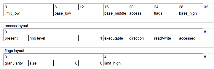
Here’s what the fields mean:
- base a 32 bit value describing where the segment begins
- limit a 20 bit value describing where the segment ends, can be multiplied by 4096 if granularity = 1
- present must be 1 for the entry to be valid
- ring level an int between 0-3 indicating the kernel Ring Level
- direction
- 0 = segment grows up from base, 1 = segment grows down for a data segment
- 0 = can only execute from ring level, 1 = prevent jumping to higher ring levels
- read/write if you can read/write to this segment
- accessed if the CPU has accessed this segment
- granularity 0 = limit is in 1 byte blocks, 1 = limit is multiples of 4KB blocks
- size 0 = 16 bit mode, 1 = 32 bit protected mode
We’ll define this directly in assembly:
gdt_start:
    dq 0x0
gdt_code:
    dw 0xFFFF
    dw 0x0
    db 0x0
    db 10011010b
    db 11001111b
    db 0x0
gdt_data:
    dw 0xFFFF
    dw 0x0
    db 0x0
    db 10010010b
    db 11001111b
    db 0x0
gdt_end:
To actually load this we also need a gdt pointer structure. This is a 16 bit field containing the GDT size followed by a 32 bit pointer to the structure itself. We’ll also define the CODE_SEG and DATA_SEG value which are offsets into the gdt for use later:
gdt_pointer:
    dw gdt_end - gdt_start
    dd gdt_start
CODE_SEG equ gdt_code - gdt_start
DATA_SEG equ gdt_data - gdt_start
At this point we have enough to get into 32-bit mode! Let’s tell nasm to output 32 bit now. We’ll also set the remaining segments to point at the data segment.
bits 32
boot2:
    mov ax, DATA_SEG
    mov ds, ax
    mov es, ax
    mov fs, ax
    mov gs, ax
    mov ss, ax
Writing to the VGA Text Buffer
Finally let’s write ‘Hello world!’ to the screen from Protected Mode! We can’t call the BIOS any more but we can write to the VGA text buffer directly. This is memory mapped to location 0xb8000. Each character on screen has this layout:

The top byte defines the character colour in the buffer as an int value from 0-15 with 0 = black, 1 = blue and 15 = white. The bottom byte defines an ASCII code point. Using this information we can write some assembly that writes ‘Hello World’ in blue text:
    mov esi,hello
    mov ebx,0xb8000
.loop:
    lodsb
    or al,al
    jz halt
    or eax,0x0100
    mov word [ebx], ax
    add ebx,2
    jmp .loop
halt:
    cli
    hlt
hello: db "Hello world!",0
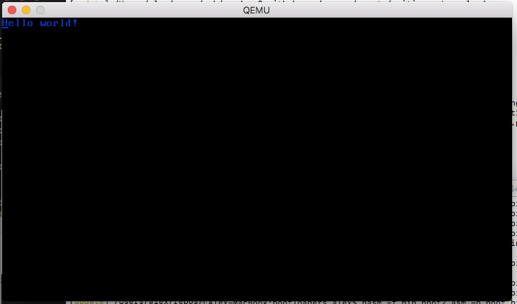
Let’s run the thing!
We finally have everything! Save the whole thing as a boot2.asm file (source available here) then run it with nasm -f bin boot2.asm && qemu-system-x86_64 -fda boot.bin. You should get something like this!
Next Steps
Amazing! In part 3 of this series we’ll look at loading a C++ function that we’ve compiled into memory and then call it from our bootloader. Almost there!